Analysis of surface quenching process of curved surface
Foreword
This standard is based on the rules given in GB/T 1.1-2009.
This standard was proposed by the Ministry of Industry and Information Technology of the People's Republic of China.
This standard is under the jurisdiction of the National Solar Photovoltaic Energy System Standardization Technical Committee (SAC/TC 90).
This standard was drafted by: Yunnan Normal University, Yunnan Semiconductor Device Factory, Beijing Rijia Power Co., Ltd., Tianjin Power Supply Department of the Ministry of Information Industry
Institute, Xinjiang New Energy Co., Ltd., Kunming Photovoltaic Technology Co., Ltd.
The main drafters of this standard: Liu Zuming, Li Jiehui, Yang Hongyan, Zhou Lixin, recreation.
introduction
The independent photovoltaic system is a power generation system that directly converts the solar radiation energy emitted by a person into electricity, and does not connect with the utility grid. For the technical requirements of the distribution system and distribution system engineering in an independent photovoltaic system, due to relatively complete relevant standards, it can be implemented according to the relevant transmission and distribution standards according to the design voltage level. For the civil engineering part, according to the relevant building standard requirements, according to the design requirements, which need to emphasize or special requirements in accordance with Chapter 5 "other requirements" to implement.
1 Scope
This standard specifies the requirements of independent photovoltaic systems, subsystem specifications and requirements, on-site testing and system evaluation.
This standard applies to ground independent photovoltaic systems with a power of at least 1 kW. Concentrator photovoltaic systems, other complementary independent power supply systems and photovoltaic-related parts can refer to this standard.
Note: The system power refers to the sum of the power of the used PV modules under the ground standard test conditions.
2 normative references
The following documents are indispensable for the application of this document. For dated references, only dated versions apply to this document. For undated references, the latest edition (including all amendments) applies to this document.
GB/T 2828.1 Count Sampling Inspection Procedures Part 1: Batch Inspection Sampling Plans Retrieved by Acceptance Quality Limit (AQL)
GB/T 3859.1 Requirements for basic requirements of semiconductor converters
GB/T 9535 ground crystalline silicon photovoltaic module design, identification and stereotypes (IEC 61215)
GB 12527 overhead insulated cable with rated voltage of 1 kV and below
GB/T 13337.1 fixed acid-proof lead-acid battery technical conditions
In-situ measurements of IV characteristics of GB/T 18210 crystalline silicon photovoltaic (PV) arrays (IEC 61829)
GB/T 18911-2002 Design and identification of thin-film photovoltaic modules for use on the ground (IEC 61646)
GB/T 19001 Quality Management System Requirements (ISO 9001)
GB 50054-1995 Design Specification for Low Voltage Distribution
GB 50094 design code for building lightning protection
GB 50164 concrete quality control standard
Code for construction and acceptance of GB 50168 electrical installation project cable line
GB 50169 Electrical Installation Project Grounding Device Construction and Acceptance Specifications
GB 50172-1992 Installation specification for electrical installations
GB 50202-2002 Specification for Construction Quality Acceptance of Foundation Engineering for Buildings
GB 50205-2001 Specification for Construction Quality Acceptance of Steel Structure Engineering
GB 50258 electrical installation project 1 kV and below wiring project construction and acceptance specifications
DL 408 Electrical Safety Code of Work
DL/T 464.1-5 Overhead insulated wire fittings and insulation parts for rated voltages up to 1 kV
DL 477 rural low voltage electrical safety working regulations
DL 499 rural low voltage power technical specification
DL 5009.2 Safety Regulations for Electric Power Construction
DL 5027 Typical Fire Regulations for Electrical Equipment
Guidelines for Overvoltage Protection of SJ/T 11127 Photovoltaic Power Generation System (IEC 61173)
YD/T 799-2002 Valve Controlled Sealed Lead Acid Battery for Communication
IEC 61683 Photovoltaic systems-Power conditioners-Procedure formeasuring efficiency
IEC 61724 photovoltaic system performance monitoring measurement, data exchange and analysis
3 system requirements
3.1 Composition
The independent photovoltaic system mainly includes the following subsystems:
- Main control and monitoring subsystems: Monitor the overall operation of the photovoltaic power generation system and the interaction between the various subsystems, and it can also act on the load;
- Photovoltaic subsystem: a unit that converts direct solar radiation energy into direct current energy;
― Power Regulator: Transforms electrical energy into one or more systems suitable for subsequent load use;
―Energy storage subsystem: It is used to store electrical energy and meet the requirements of continuous power consumption. Including energy storage devices and input-output control devices.
In a particular photovoltaic power system design, certain parts of the above subsystems may be omitted, and some of the components of the subsystems may appear in a single or combined form. For example, the control equipment used in the PV system generally has both the main control and monitoring functions and the input-output control function in the energy storage subsystem; the inverter may have some functions of the power conditioner, but may also include some energy storage subsystems. Lose people an output control function.
As an independent photovoltaic system and general load interface power distribution system, generally not as part of an independent photovoltaic system, but in the photovoltaic system engineering construction often supporting distribution system engineering construction, so in this standard, the distribution system will not be detailed Requirements, its basic requirements, see Chapter 5 "Other requirements."
The main components of the system should use qualified products that have passed relevant quality inspection or certification.
3.2 System power supply protection rate
The system power supply guarantee rate, that is, the percentage of the time that the load can be supplied during the year. The first failure of the system is due to the lack of power generation due to continuous rainy days, the storage energy of the energy storage subsystem can not meet the power consumption of the system load, and the second is due to system failure. The former depends on the system design configuration, and the latter depends on the system reliability and maintenance response time.
The determination of the system power supply guarantee rate mainly depends on the power requirements. The power supply protection rate for conventional power systems is generally 80% to 90%. For special systems that require high power supply protection rates, multiple power supply types should be considered to be complementary.
3.3 Safety Requirements
The system should meet the basic safety requirements:
- Construction safety: The requirements of 3.3 in GB 50054-1995 should be met. For placing fixed acid-proof explosion-proof lead-acid batteries
The battery room must have forced ventilation protection; it should meet the requirements of acid proof and explosion proof;
―Electrical safety: The corresponding regulations of GB 50054-1995 should be complied with. The exposed parts of all electrical equipment in the system should be provided with safety
Full warning signs; system overvoltage protection shall comply with SJ/T 11127;
―Fire safety: The requirements of DL 5027 should be met. The battery room should be equipped with a fire extinguisher.
3.4 Information requirements
The independent photovoltaic system should have complete technical data, including design, equipment and materials, project management, training, operation management and other relevant information.
System design data mainly includes design specifications, system configuration lists, and/or design drawings.
The system equipment and material data include at least the relevant information of the main equipment and materials of each subsystem, such as: certificate, inspection and/or related certification report, instruction manual and/or technical specification.
The engineering data in the project management data includes the main equipment unpacking inspection records, system installation records, etc. Civil engineering and transmission engineering data should meet the requirements of Chapter 5 "Other requirements".
The training materials mainly include training materials and graphic illustrations used by users.
Operation management information mainly includes operation management procedures, operation records, maintenance operation procedures, and troubleshooting guides.
All operation IDs must be in Chinese or have Chinese comments. In ethnic minority areas, there should be ethnic minority characters in the operation logos, and in addition to the Chinese version, the operating logos should also be added to the minority language versions.
3.5 Design Principles
The design of an independent photovoltaic system should be based on the premise of meeting the requirement of system load power supply guarantee rate, comprehensive evaluation of environmental conditions and system performance, appropriate system scalability, and design of each subsystem. Photovoltaic system design is a very complex process. This standard only gives some general principles and requirements. The detailed requirements are given by future PV system design specifications.
Photovoltaic system load estimation is a key link in system design and cost accounting. The power of the load device can be obtained through measurement or product technical data, or refer to the relevant data of the same type of equipment. The time when the load device works can be calculated. Based on the measured load, the possible changes in the load should also be analyzed and evaluated to make design adjustments. When there is a DC load, the system DC voltage is generally selected as the maximum load DC voltage or the maximum load DC voltage; the AC voltage is generally selected according to the requirements of the load device.
The designed power of the PV subsystem should be designed for the monthly surface radiation of the inclined surface, and the standard daily power generation quantity multiplied by the photovoltaic system efficiency to meet the system load daily electricity demand. The design of the annual photovoltaic system with a balanced load on the monthly inclined surface should be less than the annual average daily radiation of the inclined surface, which is generally equal to the minimum monthly average radiation amount of radiation on the inclined surface. Unbalanced load The design of an independent photovoltaic system is mainly based on obtaining the maximum solar radiation during the load use period. PV subsystem voltage design should fully consider the voltage-temperature relationship of the photovoltaic system: The design operating voltage shall ensure that the battery is effectively charged throughout the year, and the maximum voltage that the system may reach may not exceed the maximum system voltage that a single photovoltaic module can withstand.
Note: The standard power generation capacity of the PV subsystem is equal to the power of the square array multiplied by the standard equivalent power generation. For the calculation of standard equivalent power generation, see IEC 61724. Photovoltaic system efficiency mainly consists of the temperature loss, combined loss, and occlusion loss of the photovoltaic subsystem, the charge and discharge efficiency of the energy storage subsystem, the inverter efficiency of the power conditioner, the power regulation loss, and the loss of the Hanning power grid. The efficiency of crystalline silicon photovoltaic system can be selected as reference 0.51.
In stand-alone PV systems, energy-storage batteries that are suitable for deep discharge and have a long cycle life should be used. The capacity of an independent photovoltaic system battery shall be able to store the electrical energy required to meet the load's power consumption within a certain range of the amount of radiation on the inclined surface. The design of the battery capacity should take into consideration the design life of the battery, the load condition, the unevenness of radiation on the inclined plane, the power of the PV subsystem, and the system efficiency. When the battery usage temperature deviates from the standard temperature, the battery design capacity should be properly adjusted according to the operating temperature.
For the determined power supply security rate, when the design power of the PV subsystem is small, the battery configuration capacity of the system is increased. The relationship between the PV subsystem power variation and the battery capacity variation depends on the radiation status of the PV system construction site. According to the principle of optimum design of PV subsystem power and battery capacity that meets the requirements of system power supply guarantee rate and the lowest overall system construction cost, it is appropriate to design the monthly sloping surface daily radiation quantity based on the minimum monthly average sloping surface daily radiation quantity (or close to value). . When the PV subsystem design margin is not high, the battery capacity should not be selected too large; when the PV subsystem design margin is large, the battery capacity should not be selected too small.
Note: The design capacity of the crystalline silicon photovoltaic system battery should generally be not less than 2.44 times the daily generation capacity of the photovoltaic subsystem design standard.
The capacity of the power conditioner should take into account the power of the load, the power factor, the simultaneous rate of power usage, the load factor of the inverter and the unbalance coefficient of each phase.
The system design should have redundancy. The power regulator should have limitations and protection functions to meet the requirements of the system's reliable operation. For the system with high power supply guarantee rate, the key equipment backup or modular redundant configuration can be considered to improve the system's reliability. Sex.
System design should also consider explosion-proof, anti-static, anti-theft and other security design.
The system design should consider the geographical conditions of the establishment site, such as high altitude, coastal areas, islands and wet environments.
For systems with higher altitudes, design should take full account of the special geographical conditions of the site establishment, such as: low air pressure, low air density, poor heat dissipation conditions, etc., to ensure that the pressure range of the exhaust valve of sealed batteries and the electronic components Thermal characteristics. For systems with high or low ambient temperature, in addition to the relevant requirements for the temperature adaptability of key equipment design and selection, special consideration should also be given to temperature control design of the battery room.
Systems engineering in earthquake-prone areas should consider corresponding seismic design, including civil engineering, square array support, and battery racks.
The environmental meteorological data used in the design mainly include: site location (including location, latitude, longitude and altitude, etc.), meteorological data (including monthly total solar radiation, direct radiation or scattered radiation, annual average temperature, maximum and minimum temperatures, and Long continuous cloudy days, maximum wind speed, hail, snowfall, lightning, etc.). In the absence of complete meteorological data, reference may be made to meteorological data at similar conditions or using empirical formulae/methods for estimation.
Comprehensive optimization of system design should be carried out in order to improve system efficiency and better meet system power supply guarantee requirements. In the design of system parameters, the corresponding technical parameter values ​​recommended by this technical specification should be selected as far as possible, and can also be designed according to the user's special requirements. Since the system design involves environmental meteorological parameters such as solar radiation and other complex calculations, computer-aided design should be adopted.
The main content of the independent photovoltaic system design:
a) Calculate the load power consumption and determine the power supply voltage level;
b) According to the load power and system power supply guarantee rate requirements, combined with solar radiation resources, site conditions, system efficiency factors, choose the azimuth, optimize the tilt angle, calculate the amount of photovoltaic modules, determine the selection of photovoltaic modules, square array electrical structure design;
c) Comprehensive load power, system power supply guarantee rate requirements, meteorological conditions, system power, energy storage device (battery) characteristics, calculation of energy storage device (battery) capacity, optimization of photovoltaic subsystem power and battery capacity configuration. Select the battery voltage according to the system DC voltage or inverter requirements.
d) Master and monitor subsystem design.
e) Power Regulator design.
f) Engineering design (possibly including land occupation, fences, photovoltaic square arrays, cable trenches, machine rooms, lightning protection, grounding, drainage systems, etc.).
g) Distribution system design (optional).
4 subsystem specifications and requirements
4.1 Main Control and Monitoring Subsystem
The main control and monitoring subsystems mainly include (but are not limited to) the following monitoring and control functions:
―System data signal sensing and acquisition;
―System data processing, recording, transmission and display;
―Energy transmission control;
―Startup and control of equipment;
-protection.
To simplify design and use, some or all of the functions of the master and monitor subsystems may be included in other subsystems. This standard is standardized in the corresponding subsystems.
4.2 PV subsystem
Photovoltaic subsystems mainly include photovoltaic modules, foundations, supporting structures, internal electrical connections, protective facilities, and grounding.
4.2. Flight General Requirements
Photovoltaic subsystems are generally designed to meet the average or peak demand of the system's annual power output. The size of the PV subsystem can be determined based on the specific load that needs to be met, or on the basis of an ordinary load range and system performance price ratios. The result is OK.
The square array bracket can be fixed or intermittent/continuously adjustable. The system design should select the proper orientation for the square array. The photovoltaic modules should generally face the south; in the case of a specific geographical environment, such as avoiding sheltering, consideration can be given to Adjust the design within ±20° South.
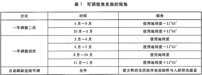
Adjustable angle brackets are generally adjusted in the following manner: one time for adjustment, one time for adjustment and one year for adjustment, and automatic tracking for continuous adjustment. Refer to Table 1 for the corresponding time and inclination values.
The best choice for the installation angle of fixed arrays depends on many factors such as: geographical location, annual solar radiation distribution, direct radiation and scattered radiation ratio, load power requirements and specific site conditions. For the whole year's balanced load, the square array angle of the independent photovoltaic system should maximize the radiation of the minimum monthly slope, and the non-equilibrium load of the independent photovoltaic system should consider the square array angle of inclination to maximize the radiation amount of the inclined surface during the large load Change.
The IV characteristic curves of photovoltaic modules connected in series and in parallel according to a certain method should have good consistency in order to reduce the loss of combination of square arrays; the combined loss of optimized PV subsystem design should not exceed 8%.
Note: The system combination loss refers to the ratio of the sum of the PV module power used to the PV subsystem output power divided by the PV subsystem output power (under ground standard conditions).
The design of the support structure of the phalanx should comprehensively consider the geographical environment, the status of the phalanx field, and the specifications of the photovoltaic modules, so as to ensure the firmness, safety and reliability of the photovoltaic phalanx.
4.2.2 Photovoltaic field requirements
The selection of the square field should avoid the influence of shadows, and there should be enough space between the arrays to ensure that the PV modules are not shaded between 9 am and 3 pm local time of the year.
For photovoltaic systems installed on the ground, the field surface shall be compacted and the soft soil shall be reinforced. For areas with annual precipitation above 900mm, drainage facilities shall be provided, and the sandstone layer shall be laid on the compacted surface to reduce the Small mud water splashes.
The square base should meet the requirements of Chapter 5 of GB 50202-2002.
4.2.3 Technical Specifications and Requirements of Major Components and Components
4.2.3.1 Photovoltaic modules
Photovoltaic modules must meet the requirements of product standards, and pass the qualification and conformity of the qualified products according to the requirements of GB/T 9535 or GB/T 18911-2002; they shall be manufactured from materials and components that meet the requirements of the corresponding drawings and Manufacturers routine testing, quality control and product acceptance procedures.
The component products shall be complete, and each photovoltaic component mark shall have the requirements of Chapter 4 of GB/T 9535-1998 or GB/T 18911-2002, and be marked with rated output power (or current), rated operating voltage, open circuit Voltage, short circuit current; qualified mark. Photovoltaic module products shall be accompanied by the manufacturer's instructions for storage, installation, and circuit connection, as well as quality inspection reports of qualified quality inspection centers that are approved by relevant state administrative and administrative departments. Should adopt the product production quality management system to meet GB/T 19001 requirements of the product.
The component interconnections shall be designed in accordance with the electrical design of the square array. Each PV module shall be equipped with a bypass diode in the junction box of the module.
4.2.3.2 Connection Box (Box)
The junction box (box) is used for the connection between the sub-squares formed by the interconnection of the photovoltaic modules and the connection between the sub-array and the control room. For the multi-parallel system, it is better to group the reverse-current diodes. The capacity of the reversed-diode passing current should be greater than 150% of the short-circuit current of the series set under standard test conditions, and the peak reverse voltage should be at least twice the open-circuit voltage of the series set.
4.2.3.2.1 Structural requirements
The junction box (box) shall adopt a sealed structure and the design shall meet the requirements for outdoor use.
The junction box (box) with metal box should be reliably grounded.
For materials processed by insulating polymer materials, the selected materials shall have good weather resistance, and shall be accompanied by relevant technical materials such as the specifications of the materials used, materials certificates, etc.
4.2.3.2.2 Performance Requirements
The connection box (box) terminal design should ensure that the cable is connected reliably. There should be anti-loosening parts. For fasteners that are both conductive and fastened, copper parts should be used.
Each PV branch is connected to the incoming end of the sub-array and the outgoing end of the sub-array, and the insulation resistance between the terminal and the grounding end of the connection box (box) shall not be less than 10MΩ (DC500V).
4.2.3.3 Connecting Cables
The output cable of the junction box (box) shall be weather-resistant, UV-resistant, and other anti-aging cables. The cable diameter shall meet the requirements of the maximum output current of the square array in order to reduce the loss of the line. The cable and the terminal should be connected tightly without looseness.
4.2.3.4 Square Braces
Photovoltaic subsystems can be installed in many forms, such as ground, roof, and building integration. The installation form of the roof and building integration shall consider the bearing surface load capacity, and the engineering design shall comply with the relevant building standard requirements.
The ground-mounted PV array bracket should adopt steel structure. The bracket design should ensure that the PV module and the bracket are connected firmly and reliably. The base and the foundation should be firmly connected. The module should not be less than 0.6m away from the ground. Considering the site environment and weather conditions, it may be appropriate. Adjustment.
The bracket should have sufficient strength to meet the static and dynamic load requirements of the square array. In areas with large winds, the space between the PV modules or the PV arrays should be taken into consideration or the brackets should be reasonably arranged to reduce the dynamic loads. The design strength should be sufficient. The largest wind load requirement in local history ensures that the array is firm, safe, and reliable. The steel structure bracket should meet the requirements of GB 50205-2001. The brackets of other rigid structural materials should not be lower than the performance requirements of the steel structure bracket.
The square array bracket should be ensured to be reliably grounded, and the grounding resistance of the grounding body should not be greater than 10Ω. The grounding should be treated with anti-corrosion and resistance-reduction, and meet the requirements of Chapter 5.
The square bracket steel structure should be treated with anti-rust coating to meet the long-term outdoor use requirements. Photovoltaic modules and square array fasteners should be made of stainless steel or surface-coated metal parts or other anti-corrosion materials with sufficient strength.
4.3 Energy Storage Subsystem
The input-output control function of the energy storage subsystem is implemented by dedicated control equipment or other subsystems (main control and monitoring, power regulators), such as control equipment, inverter equipment, etc. System specifications.
Lead-acid batteries are currently more suitable energy storage devices for independent photovoltaic systems. This standard specifies the technical requirements for fixed anti-acid, valve-regulated sealed lead-acid batteries. Other types of batteries can refer to the relevant national standards or industry standards.
4.3.1 General Requirements
Each battery shall have a production certificate. The type and date of manufacture of the battery shall be indicated on the certificate. The manufacturer shall provide a quality inspection report issued by a quality inspection agency approved by the relevant administrative department of the country with the same type of product. The production time of the battery should be as close as possible to the date of shipment.
Storage time should not exceed 6 months, and its charge should not be less than 80% after 90 days. The signs, packaging, transportation and storage of batteries shall comply with the provisions of Chapter 8 of YD/T 799-2002. The same charge and discharge control battery should use the same manufacturer. If the products of the same specification and capacity do not belong to the same batch of products, the interval between production dates must not exceed one month.
For current lead-acid batteries commonly used in stand-alone photovoltaic systems, the design-day discharge depth should not exceed 30%, and the maximum depth of discharge should not exceed 80% (in case of parallel use, the maximum allowable depth of discharge should be reduced); for charging according to the battery voltage The discharge control system should fully consider the discharge rate of the battery when designing the discharge control voltage point to ensure the battery design discharge depth.
The product shall provide the cycle life indicator at the design depth of discharge and the limit discharge depth.
The operating temperature of the battery can be in accordance with the product requirements. The recommended temperature range is 5°C to 30°C.
The appearance of the battery must not be deformed, leaking, cracks, and smudges; the mark must be clear.
4.3.2 Pavilion controlled sealed lead acid battery
Capacity, large current discharge, capacity preservation rate, sealing reaction efficiency, anti-fog performance, safety valve requirements, overcharge resistance, connection voltage drop between batteries, and explosion-proof performance index shall meet the requirements of YD/T 799-2002.
Single cell battery voltage equalization should meet the following requirements:
a) The difference between the highest and lowest values ​​of the open circuit voltage between the batteries shall not exceed 20mV (single 2V series).
b) After 3-6 months of operation, the difference between the float voltage and the average voltage is less than 5%.
4.3.3 Fixed Acid Resistant Lead Acid Battery
Battery tank, airtightness, capacity, self-discharge, acid resistance, safety performance, maximum discharge current, resistance to trickle charge and electrolyte storage, life, sealing agent performance, storage period shall meet the requirements of GB/T 13337.1.
4.3.4 Insulation performance
The insulation resistance of the battery to the ground should not be less than 10MΩ (DC500V).
4.3.5 Temperature compensation of battery float voltage
The float charge voltage of the battery is a specified value at 25°C. When the ambient temperature changes, the float charge voltage of the VRLA battery must be temperature compensated. When the temperature is higher than 25°C, the voltage is subtracted from the float voltage. The amount of compensation, if not, is added, and the product should explicitly give the temperature compensation coefficient.
4.3.6 Battery Parallel Connection
The maximum number of batteries in parallel is no more than 6 groups.
4.3.7 Battery Installation
Battery installation meets the requirements of 2.1.3 in GB 50172-1992. When the battery is connected with the fastening nut, the torque should meet the corresponding design requirements. Initial charging should be carried out according to the manufacturer's regulations.
4.4 Power Regulator
The power regulator is mainly composed of one or more of the following components: a DC regulator, a DC/DC interface, an inverter, an AC/AC interface, and a partial master control and monitoring subsystem. In order to achieve higher efficiency and reliability, it is advisable to use an integrated optimization design of the machine.
Control equipments and inverter equipments are relatively common devices for realizing power regulator functions in current photovoltaic systems. This standard specifies technical requirements for control equipment and inverter equipment. Equipment technical parameters should adopt the recommended values ​​of this standard, and can also be designed according to the user's special requirements.
4.4.1 General requirements
The power conditioner equipment selection should meet the design function requirements of the photovoltaic system, and the coordination and matching of the functions and/or power (capacity) should be considered among the functional devices.
The power regulator equipment shall be a qualified product that meets product standards and passes inspection. The efficiency measurement program shall refer to IEC 61683. The nameplate, grounding mark, and functional mark shall be provided at the time of delivery. The corresponding content identification shall be clear and correct. The nameplate must indicate at least the manufacturer's name, serial number, date of manufacture, and the main characteristics of the device.
The equipment rack should have enough rigidity and be equipped with mounting holes and lifting devices; the operation and operation of the device should be suitable for personnel operation; should be reliable grounding, product structure protection level should not be less than IP200 equipment, the main components must be selected to meet product standards Qualified products that have passed the final test. The installation of components shall comply with the specifications in the product specification, design documents or drawings. Indicates that the instrument range should be selected properly, and the maximum value of the measurement should be more than 85% of full scale.
Equipment insulation performance should meet the requirements of GB/T 3859.1. The vibration resistance performance should be able to work properly after 30 minutes of vibration in the triaxial direction with a frequency of 10 Hz to 55 Hz and an amplitude of 0.35 mm.
The normal environmental conditions for use of the product are:
a) The ambient temperature is in the range of 0°C to +40°C;
b) When the ambient temperature is below 20 °C, the relative humidity is not more than 90%;
c) The altitude is not more than 1000m;
d) Indoor use of non-corrosive gases and conductive dust.
When the actual use of the product's environmental conditions exceeds the normal range of use, it should be negotiated with the manufacturer for appropriate corrections.
4.4.2 Control Equipment
Control equipment refers to the implementation of DC regulators, DC/DC interfaces, and some (or all) of the main control and monitoring functions in an independent photovoltaic system.
device of. The selection of control equipment power should match the power of the photovoltaic array. The main characteristic parameters of the control equipment include: nominal power (or maximum operating current), nominal voltage, and input voltage range.
4.4.2.1 Technical Parameters
a) DC nominal power should be selected from the following values ​​(kW): 1, 3, 5, (7.5), 10, 15, 20, 30, 50, 80, 100, 125, 150.200;
Note: Parentheses are not preferred values.
b) The maximum DC operating current should be selected from the following values ​​(A): 5,10,20,50.100,(150),200,250,300,400,500;
Note: Parentheses are not preferred values.
c) DC nominal voltage should be selected from the following values ​​(V): 24, 48, (60), 120, 240, 360.480;
Note: Parentheses are not preferred values. When selecting a higher system DC voltage, care should be taken to select a PV module with a high system voltage.
d) The DC input voltage range should not be less than the nominal voltage range of 80% to 200%.
4.4.2.2 Protection Features
Control equipment should have the following protection features:
a) load, battery short circuit protection;
b) Reverse polarity protection of solar cells and batteries;
c) Battery reverse discharge protection to the solar cell.
4.4.2.3 Control Functions
Control equipment should have the following control functions:
a) Battery charging control according to battery capacity or voltage. When the battery capacity or voltage reaches the charging control setting value, the control device can shut off the battery charging circuit; when the battery capacity or voltage is lower than the charging control setting value, the control device The battery charging circuit can be automatically switched back on; the setpoints can be adjusted and changed.
b) According to the battery capacity or voltage battery discharge control, when the battery capacity or voltage reaches the discharge control set value, the control device can shut off the battery discharge circuit; When the battery capacity or voltage is higher than the discharge control to restore the set value, control The device can automatically restore the battery discharge circuit; the setpoints can be adjusted and changed. The discharge control setting value and the discharge control recovery setting value shall be set on the basis of the battery discharge rate according to the battery parameters to meet the designed battery discharge depth requirement; the discharge control recovery setting value should be set to enable the battery capacity to be restored to 90%.
Note: Battery discharge control can also be achieved by inverter equipment.
c) When the operating temperature of the storage battery changes, the control device shall have temperature compensation control, and the temperature compensation coefficient shall be determined according to the battery parameters.
4.4.2.4 Static Characteristics Requirements
The static characteristics of the control equipment should meet the following requirements:
a) Under nominal input conditions, the efficiency of the control equipment at full load (output nominal power) shall not be less than 95%;
b) At nominal input voltage, the no-load loss of the control equipment shall be no more than 0.5% of its nominal power;
c) In the rated input condition, the noise at 1m away from the equipment at the full load (output nominal power) of the control equipment shall not exceed 60dB (A sound level).
4.4.2.5 Dynamic Characteristics Requirements
The dynamic characteristics of the control equipment should meet the following requirements:
― The control equipment should be able to withstand the abrupt cyclical impact of the input voltage from the nominal voltage to the maximum input voltage ((2 times the nominal voltage);
―The control equipment should be able to withstand the abrupt cyclical impact of the input current from zero to the maximum allowable input current.
4.4.2.6 Measurement Display
The control equipment shall have a measurement display of the main operating parameters and an indication of the operating status. The parameter measurement accuracy should not be less than 1.5. The measurement display parameters include at least the PV array current and the battery voltage and current; the status indicates the battery status and the PV array status.
4.4.2.7 Remote Monitoring Function
The control equipment should have a remote monitoring function. The interface should adopt RS-232C or RS-485.
4.4.3 Inverter Equipment
Inverter equipment refers to equipment that implements inverters, AC/AC interfaces, and some (or all) of the main control and monitoring functions in an independent photovoltaic system. The selection of inverter equipment capacity should match the power of the maximum peak load. The main characteristic parameters of inverter equipment include: nominal capacity, input nominal voltage, input voltage range, output voltage, output frequency, and output phase number.
4.4.3.1 Technical Parameters
a) AC nominal capacity (power factor 0.8) shall be selected from the following values ​​(kVA): 1, 3.5, (7.5), 10.15.20, 30, 50, 80, 100, 125, 150, 200.
Note: Parentheses are not preferred values.
b) DC input nominal voltage shall be selected from the following values ​​(V): 24.48, (60), (110), 120, (220), 240, 360, 480,
Note: Parentheses are not preferred values. When selecting a higher system DC voltage, care should be taken to select a PV module with a high system voltage.
c) The DC input voltage range shall not be less than the nominal voltage range of 80% to 140%.
d) AC output is sine wave, rated frequency is 50 Hz, rated voltage is single-phase 220V, three-phase 380V.
4.4.3.2 Protection Functions
The inverter equipment should have the following protection functions:
DC input overvoltage, undervoltage, and polarity reverse protection; when DC undervoltage protection is used as a battery over-discharge protection action, the battery capacity should be restored to more than 90% to automatically resume operation.
Output short circuit, over voltage, under voltage, overload, over frequency, under frequency protection.
4.4.3.3 Static Characteristics Requirements
The static characteristics of inverter equipment should meet the following requirements:
a) The output capacity is within the input voltage variation range. When a 100% nominal value (power factor 0.8), the change of the AC frequency output from the inverter equipment should not exceed 50Hz±1Hz; the change of the AC voltage should not exceed ±5% of the rated voltage; the total harmonic of the AC voltage should not exceed 5 %, each harmonic should not exceed 3%;
b) In the range of input voltage variation, when the output capacity is 10% to 100% of the nominal value, the crest factor of the inverter output should not be less than 2.5;
C) Under nominal input conditions, the full load (resistive load) efficiency of the inverter equipment shall be not less than 85% when the nominal capacity is less than 10 kVA, and shall not be less than 90% when the nominal capacity is not less than 10 kVA;
d). In rated input voltage, the no-load loss of inverter equipment should be no more than 2.5% when the nominal capacity is less than 10kVA, and not more than 1.5% when the nominal capacity is not less than 10kVA;
e) In the rated input condition, when the inverter equipment is full load (resistive load), the noise from the equipment 1m should not exceed 60dB (A sound level);
f) For three-phase inverter equipment, when the three-phase load is extremely unbalanced under the rated input voltage (one phase is 0, the other two phases are 100%, or one phase is 100%, and the other two phases are 0), The unbalance of the three-phase output voltage should not exceed 10%.
4.4.3.4 Dynamic Characteristics Requirements
The dynamic characteristics of inverter equipment should meet the following requirements:
a) The inverter equipment shall be capable of withstanding the abrupt cyclical impact of the input voltage from the nominal voltage to the maximum input voltage (1.4 times the nominal voltage), and the peak value of the output voltage mutation shall not exceed 10% of the rated output voltage;
b) The inverter equipment shall be capable of withstanding abrupt cyclical impacts of the output capacity from zero to full load, and the peak value of the sudden output voltage shall not exceed 10% of the rated output voltage;
C) In the rated input voltage, the inverter equipment should be able to withstand output overload 120%, 1min, withstand output overload 150%, 10s,
4.4.3.5 Measurement Display
Inverter equipment should have a measurement display of the main operating parameters and an indication of operating status. The parameter side accuracy should not be less than 1.5. The measurement display parameters include at least the DC input voltage, input current, AC output voltage, and output current (capacity); the status indication shows the state of the inverter (operation, fault, shutdown, etc.).
4.4.3.6 Remote Monitoring Function
Inverter equipment should have a remote monitoring function, the interface should use RS-232C or RS-485.
4.4.4 AC (Direct) Current Distribution Equipment
Cross-current (straight-flow) power distribution equipment refers to devices that implement AC/AC (DC/DC) interfaces and some of the main control and monitoring functions in an independent photovoltaic system. The selection of the capacity of the AC (straight-flow) distribution equipment should be matched with the input power supply equipment and the output power load capacity of the input. The main characteristic parameters of the AC/DC flow distribution equipment include nominal voltage and nominal current.
4.4.4.1 Technical Specifications
a) The nominal current should be selected from the following values ​​(A): 5.10,20,50,100,(150),200,250.300,400,500;
Note: Parentheses are not preferred values.
b) The nominal voltage shall be selected from the following values ​​(V): DC: 24, 48, 60, 110, 220; AC: 220, 380;
c) Input, output voltage range shall be within the range of 80% to 140% of the nominal voltage.
4.4.4.2 Protection Functions
Cross-current (straight-flow) power distribution equipment should have at least the following protection functions:
a)输出过载ã€çŸè·¯ä¿æŠ¤ï¼›
b)过电压ä¿æŠ¤ï¼ˆå«é›·å‡»ä¿æŠ¤ï¼‰ã€‚
4.4.4.3测é‡æ˜¾ç¤º
交(直)æµé…电设备应有主è¦è¿è¡Œå‚数的测é‡æ˜¾ç¤ºå’Œè¿è¡ŒçŠ¶æ€çš„指示。å‚数测é‡ç²¾åº¦åº”ä¸ä½ŽäºŽ1.5级。测é‡æ˜¾ç¤ºå‚数至少包括输出电æµï¼ˆæˆ–输出容é‡ï¼‰ã€è¾“出电压ã€ç”¨ç”µé‡ï¼›è¿è¡ŒçŠ¶æ€æŒ‡ç¤ºè‡³å°‘应包括交(直)æµé…电设备状æ€ï¼ˆè¿è¡Œã€æ•…éšœç‰ï¼‰ã€‚
5其他è¦æ±‚
é…电设备的布置应按GB 50054-1995第3ç« çš„è¦æ±‚。
è“„ç”µæ± åº”è£…ç½®åœ¨å•ç‹¬çš„å®¤å†…ï¼Œè“„ç”µæ± å®¤çš„åœ°é¢è½½è·åº”å……åˆ†è€ƒè™‘èƒ½å®‰å…¨æ‰¿è½½è“„ç”µæ± çš„é‡é‡ï¼Œåº”æœ‰é€‚åº¦çš„é€šé£Žï¼Œæ ¹æ®çŽ¯å¢ƒæ¡ä»¶åº”采å–温度调控措施,使室内温度ä¿è¯è“„ç”µæ± å®‰å…¨å¯é 工作。使用防酸隔爆å¼é“…é…¸è“„ç”µæ± çš„ï¼Œè“„ç”µæ± å®¤è¿˜åº”è€ƒè™‘é˜²é…¸ã€é˜²çˆ†ã€‚
机房设计必须考虑能达到二å年以上的使用寿命。
机房消防应符åˆDL 5027è¦æ±‚。机房内应放置消防设施。
æ³¨ï¼šè“„ç”µæ± å®¤çç«å™¨åº”放在门外。
å…‰ä¼ç³»ç»Ÿå›´æ 或围墙应牢固å¯é ,高度宜ä¸ä½ŽäºŽ1.5m,è·å…‰ä¼æ–¹é˜µçš„è·ç¦»åº”符åˆ6.2.4.1ä¸f)çš„è¦æ±‚ï¼›
å¹´é™æ°´é‡åœ¨900mm以上的方阵场应设置排水沟;年é™æ°´é‡åœ¨900mm以内,å¯åˆ©ç”¨åœ°åŠ¿ç¼“å¡æŽ’水。
在雷区必须设置é¿é›·è£…置,设计符åˆGB 50094è¦æ±‚。机房的进线和出线应设置防雷设施。
æ··å‡åœŸå·¥ç¨‹åº”符åˆGB 50164è¦æ±‚。
基础工程应符åˆGB 50202-2002è¦æ±‚。
钢结构工程应符åˆGB 50205-2001è¦æ±‚。
架空线路应符åˆGB 12527,DL/T 464.1-5,DL 5009.2,DL 477,DL 499,DL 408åŠå…¶ä»–ç›¸å…³æ ‡å‡†è¦æ±‚。
电缆敷设应符åˆGB 50168的规定。
室内布线应符åˆGB 50258è¦æ±‚。
接地应符åˆGB 50169è¦æ±‚。
6现场验收
独立光ä¼ç³»ç»Ÿå®‰è£…完æˆï¼Œè¯•è¿è¡Œæ£å¸¸åŽï¼Œå¯è¿›è¡ŒéªŒæ”¶æ£€æŸ¥ã€‚
验收宜采用åˆéªŒæ”¶å’Œæœ€ç»ˆéªŒæ”¶ä¸¤æ¬¡éªŒæ”¶çš„模å¼ã€‚安装完æˆè¯•è¿è¡Œæ£å¸¸åŽï¼Œå¯è¿›è¡ŒåˆéªŒæ”¶æ£€æŸ¥ã€‚试è¿è¡Œä¸€å¹´åŽè¿›è¡Œæœ€ç»ˆéªŒæ”¶æ£€æŸ¥ã€‚
6.1系统综åˆè¯„ä»·
ä¾æ®3.5的原则进行系统综åˆè¯„价。
6.2现场检测
现场检测宜选择è¾ç…§è‰¯å¥½çš„当地时间ä¸åˆæ—¶æ®µè¿›è¡Œï¼Œå…‰ä¼å系统功率现场检测时è¾ç…§åº¦åº”大于700W/m2。所有检测ä¸éœ€è¦æ–开部分系统电路时应按系统相关è¦æ±‚,注æ„安全æ“作。
6.2.1主è¦ä»ªå™¨ã€è®¾å¤‡
―方阵IV特性测é‡ä»ªï¼Œç›´æµç”µåŽ‹æµ‹é‡ç²¾åº¦100,直æµç”µæµæµ‹é‡ç²¾åº¦100;
―å¯è°ƒç›´æµç”µæºï¼Œç²¾åº¦1%;
―兆欧表,精度ç‰çº§ä¸ä½ŽäºŽ1.5级,500V;
â€•æ¸©åº¦ä¼ æ„Ÿå™¨æˆ–å…·æœ‰æµ‹æ¸©åŠŸèƒ½çš„ä¸‡ç”¨ç”µè¡¨ï¼Œç²¾åº¦1℃;
―电æµè¡¨ï¼Œç²¾åº¦ä¸ä½ŽäºŽ0.5级;
―电压表,精度ä¸ä½ŽäºŽ0.5级;
―温度计,分度值ä¸å¤§äºŽ1℃;
―直尺ã€å·å°ºï¼Œç²¾åº¦ä¸ä½ŽäºŽ0.5mm;
â€•å¯†åº¦è®¡ï¼Œæ ‡å®šç²¾åº¦ä¸ä½ŽäºŽ0.005g/cm3 ;
―试验开关,带ç弧装置;
―水平仪;
―指å—针;
―è¾å°„å¼ºåº¦è®¡æˆ–æ ‡å‡†å¤ªé˜³ç”µæ± ï¼ˆç»„ä»¶ï¼‰(C级)。
注:检测仪器ã€è®¾å¤‡é‡ç¨‹åº”符åˆå¾…检系统è¦æ±‚.
6.2.2一般性检查
按3.4è¦æ±‚进行资料审查。应具备完整设计ã€æ–½å·¥èµ„料;使用设备ã€æ料,并且工程施工应与设计一致。对质é‡ã€æ€§èƒ½æœ‰ç–‘ä¹‰çš„åº”å¯¹è®¾è®¡è¿›è¡Œè¯„å®¡æˆ–æŠ½æ ·å¤éªŒï¼Œå…¶å¤éªŒç»“æžœåº”æ»¡è¶³çŽ°è¡Œå›½å®¶æ ‡å‡†å’Œè®¾è®¡è¦æ±‚。
è¿›è¡Œç›¸å…³æ ‡è¯†æ£€æŸ¥ã€‚æ£€æŸ¥è¿è¡Œç®¡ç†èµ„料。
6.2.3安全检测
进行资料验è¯åŠç›®æµ‹ï¼ŒæŒ‰å„分项è¦æ±‚检测,应符åˆ3.3çš„è¦æ±‚。
6.2.4å…‰ä¼å系统检测
6.2.4.1工程检测
a)目测方阵支架是å¦å…·æœ‰æŽ¥åœ°å’Œé˜²é›·è£…置,测é‡æŽ¥åœ°ç”µé˜»ä¸å¤§äºŽ10Ω。
b)目测光ä¼ç»„件连线åŠè¿›äººæŽ¥çº¿ç®±ï¼ˆç›’)的连线,应走å‘åˆç†ã€æ•´é½ï¼›è¿›çº¿å”应进行防渗水处ç†ã€‚
c)目测方阵支架涂镀层是å¦ä¸€è‡´å’Œå®Œæ•´ã€‚
d)支架连接应牢固,外观整é½ã€‚测é‡æ°´å¹³ä½ç½®å差应符åˆè®¾è®¡è¦æ±‚。
e)æ–¹é˜µç´§å›ºèžºæ “è¿žæŽ¥ç¬¦åˆGB 50205-2001ä¸6.2çš„è¦æ±‚。
f)å…‰ä¼æ–¹é˜µé˜µåˆ—é—´è·æˆ–å¯èƒ½é®æŒ¡ç‰©ä¸Žæ–¹é˜µåº•è¾¹åž‚ç›´è·ç¦»åœ¨çº¬åº¦å°äºŽç‰äºŽ45。时应ä¸å°äºŽD;
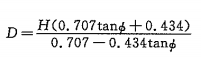
In the formula:
价―纬度(在北åŠçƒä¸ºæ£ã€å—åŠçƒä¸ºè´Ÿï¼‰ï¼›
H―光ä¼æ–¹é˜µé˜µåˆ—或é®æŒ¡ç‰©çš„最高处与å¯èƒ½è¢«é®æŒ¡ç»„件底边垂直高度差。
在纬度大于45Â°æ—¶ï¼Œæ ¹æ®å…‰ä¼æ–¹é˜µåœºå®žé™…é¢ç§¯æƒ…况,D的值å¯é€‚当é™ä½Žï¼Œä½†å…‰ä¼æ–¹é˜µé˜µåˆ—é—´è·æˆ–å¯
能é®æŒ¡ç‰©ä¸Žæ–¹é˜µåº•è¾¹åž‚ç›´è·ç¦»ä¸åº”低于纬度为45°的地区D值。
g)测é‡å…‰ä¼æ–¹é˜µçš„æ–¹ä½è§’,应符åˆ4.2.1çš„è¦æ±‚。
h)测é‡å…‰ä¼æ–¹é˜µçš„倾角,应符åˆè®¾è®¡è¦æ±‚,误差å°äºŽE3°。
i)测é‡æ–¹é˜µç»„件最低处è·åœ°é¢é«˜åº¦ï¼Œåº”符åˆè®¾è®¡è¦æ±‚。
6.2.4.2性能检测
特性检测按GB/T 18210进行,将检测数æ®å¤–æŽ¨åˆ°æ ‡å‡†æ¡ä»¶ä¸‹ä¸Žå…‰ä¼ç³»ç»Ÿé¢å®šåŠŸçŽ‡ä¹‹æ¯”应ä¸å°äºŽ92%,å³å…‰ä¼å系统方阵组åˆæŸå¤±ä¸å¤§äºŽ8%。
在相关å„æ–¹åŒæ„下;也一å¯ä¾æ®åŽ‚家的光ä¼ç»„件质é‡è®¤è¯ã€å…‰ä¼ç³»ç»Ÿå®žé™…è¿è¡Œè®°å½•ã€ç»„ä»¶æ ‡ç§°åŠŸçŽ‡åŠå®‰è£…组件总数,确认方阵总功率,如对方阵总功率有疑义,å¯æŒ‰GB/ä¹2828.1è§„å®šè¿›è¡Œç»„ä»¶æŠ½æ ·ï¼Œé€å›½å®¶è®¤å¯çš„å…‰ä¼ç»„ä»¶æµ‹è¯•æœºæž„æ£€æµ‹ï¼Œæ£€æµ‹ç»„ä»¶åœ¨æ ‡å‡†æµ‹è¯•æ¡ä»¶ä¸‹çš„实际输出功率应ä¸ä½ŽäºŽæ ‡ç§°å€¼çš„95%。
6.2.5储能å系统检测
6.2.5.1è“„ç”µæ± å¤–è§‚
ç›®æµ‹æ£€æŸ¥è“„ç”µæ± å¤–è§‚è´¨é‡åº”符åˆ4.3.1çš„è¦æ±‚
6.2.5.2è“„ç”µæ± ç«¯ç”µåŽ‹çš„å‡è¡¡æ€§æ£€æµ‹
按YD/T 799-2002ä¸6.15.1的方法进行检测,符åˆ4.3.2çš„è¦æ±‚。
6.2.5.3ç”µæ± é—´è¿žæŽ¥ä»¶ç´§å›ºæ£€æµ‹
检测连接紧固螺æ¯æ‰çŸ©åº”符åˆ4.3.7çš„è¦æ±‚。
6.2.5.4è“„ç”µæ± ç»„å®¹é‡
在相关å„æ–¹åŒæ„下,å¯ä¾æ®åŽ‚å®¶çš„è“„ç”µæ± è´¨é‡è®¤è¯ã€å…‰ä¼ç³»ç»Ÿè¿è¡Œè®°å½•ã€å®‰è£…è“„ç”µæ± æ€»æ•°ï¼Œç¡®è®¤è“„ç”µæ± ç»„çš„æ€»å®¹é‡ï¼Œå¦‚å¯¹è“„ç”µæ± ç»„çš„æ€»å®¹é‡æœ‰ç–‘义,å¯æŒ‰GB/T 2828.1è§„å®šè¿›è¡Œè“„ç”µæ± æŠ½æ ·ï¼Œé€å›½å®¶è®¤å¯çš„è“„ç”µæ± æ£€æµ‹æœºæž„è¿›è¡Œæ£€æµ‹ï¼Œæ£€æµ‹è“„ç”µæ± è´¨é‡åº”æ»¡è¶³ç›¸åº”å›½å®¶æ ‡å‡†çš„è§„å®šã€‚
6.2.6功率调节器检测
6.2.6.1一般检测
æ ¹æ®4.4.1所列å„项è¦æ±‚ï¼Œè¿›è¡Œç›®æµ‹æˆ–é€šç”¨å·¥å…·æ£€æµ‹ã€‚å¦‚åŠŸçŽ‡è°ƒèŠ‚å™¨å…·æœ‰è¿œç¨‹ç›‘æµ‹åŠŸèƒ½ï¼Œåº”æ ¹æ®ä½¿ç”¨è¯´æ˜Žæ£€éªŒå…¶åŠŸèƒ½æ˜¯å¦æ£å¸¸ã€‚
6.2.6.2控制设备检测
6.2.6.2.1ä¿æŠ¤åŠŸèƒ½æ£€æµ‹
检查设备检验报告,应具有符åˆ4.4.2.2è¦æ±‚çš„ä¿æŠ¤åŠŸèƒ½ã€‚
6.2.6.2.2控制功能检测
æ ¹æ®4.4.2.3çš„è¦æ±‚è¿›è¡Œè“„ç”µæ± å……æ”¾ç”µæŽ§åˆ¶åŠŸèƒ½è¯•éªŒã€‚æ–å¼€è“„ç”µæ± ï¼Œå°†å¯è°ƒç›´æµç”µæºæŽ¥äººæŽ§åˆ¶è®¾å¤‡çš„è“„ç”µæ± è¿žæŽ¥ç«¯ï¼Œå…‰ä¼å系统应æ£å¸¸æŽ¥äººæŽ§åˆ¶è®¾å¤‡ã€‚用å¯è°ƒç›´æµç”µæºç”µåŽ‹æ¨¡æ‹Ÿè“„ç”µæ± ç”µåŽ‹ï¼Œæ£€æµ‹åŠŸçŽ‡è°ƒèŠ‚å™¨å……æ”¾ç”µæŽ§åˆ¶åŠŸèƒ½æ˜¯å¦ç¬¦åˆè¦æ±‚ï¼ˆå½“è“„ç”µæ± æ”¾ç”µæŽ§åˆ¶åŠŸèƒ½ç”±é€†å˜å™¨å®žçŽ°æ—¶ï¼Œåˆ™æ£€æµ‹è“„ç”µæ± æ”¾ç”µæŽ§åˆ¶åŠŸèƒ½æ—¶ï¼Œåº”å°†å¯è°ƒç›´æµç”µæºç›¸åº”接人逆å˜å™¨è“„ç”µæ± è¿žæŽ¥ç«¯ï¼‰ã€‚æ£€æµ‹å€¼ä¸Žè®¾å®šå€¼å差应å°äºŽÂ±1.5%:
a)调节直æµç”µæºç”µåŽ‹ï¼Œå½“æ¨¡æ‹Ÿç”µåŽ‹é«˜äºŽè“„ç”µæ± å……ç”µæŽ§åˆ¶è®¾å®šå€¼æ—¶ï¼ˆå¦‚æœ‰å»¶æ—¶ç”µè·¯ï¼Œåˆ™å¾…å»¶æ—¶æ—¶é—´ç»“æŸï¼‰ï¼Œæ£€æŸ¥è“„ç”µæ± å……ç”µå›žè·¯å¯å¦å…³æ–ï¼›
b)é€æ¸è°ƒä½Žæ¨¡æ‹Ÿç”µåŽ‹ï¼Œå½“æ¨¡æ‹Ÿç”µåŽ‹ä½ŽäºŽè“„ç”µæ± å……ç”µæŽ§åˆ¶è®¾å®šå€¼æ—¶ï¼ˆå¦‚æœ‰å»¶æ—¶ç”µè·¯ï¼Œåˆ™å¾…å»¶æ—¶æ—¶é—´ç»“æŸï¼‰ï¼Œæ£€æŸ¥è“„ç”µæ± å……ç”µå›žè·¯å¯å¦æ¢å¤æŽ¥é€šï¼›
c)é€æ¸è°ƒä½Žæ¨¡æ‹Ÿç”µåŽ‹ï¼Œå½“æ¨¡æ‹Ÿç”µåŽ‹è¾¾åˆ°è“„ç”µæ± æ”¾ç”µæŽ§åˆ¶è®¾å®šå€¼æ—¶ï¼ˆå¦‚æœ‰å»¶æ—¶ç”µè·¯ï¼Œåˆ™å¾…å»¶æ—¶æ—¶é—´ç»“æŸï¼‰ï¼Œæ£€æŸ¥è“„ç”µæ± æ”¾ç”µå›žè·¯å¯å¦å…³æ–ï¼›
d)é€æ¸è°ƒé«˜æ¨¡æ‹Ÿç”µåŽ‹ï¼Œå½“æ¨¡æ‹Ÿç”µåŽ‹è¾¾åˆ°è“„ç”µæ± æ”¾ç”µæŽ§åˆ¶æ¢å¤è®¾å®šå€¼æ—¶ï¼ˆå¦‚有延时电路,则待延时时间结æŸï¼‰ï¼Œæ£€æŸ¥è“„ç”µæ± æ”¾ç”µå›žè·¯å¯å¦æ¢å¤æŽ¥é€šã€‚
检测完æˆåŽåº”å°†è“„ç”µæ± æ£å¸¸æŽ¥å›žç³»ç»Ÿã€‚
6.2.6.2.3特性检测
检查设备检验报告,设备特性检测应符åˆ4.4.2.4,4.4.2.5è¦æ±‚。
6.2.6.2.3.1空载æŸè€—检测
æ–开光ä¼å系统åŠè“„ç”µæ± ï¼Œå°†å¯è°ƒç›´æµç”µæºæŽ¥äººæŽ§åˆ¶è®¾å¤‡è“„ç”µæ± ç«¯ï¼Œå½“æŽ§åˆ¶è®¾å¤‡èƒ½æ£å¸¸å·¥ä½œæ—¶ï¼ŒæŽ§åˆ¶è®¾å¤‡è¾“人功率å³ä¸ºç©ºè½½æŸè€—。空载æŸè€—应符åˆ4.4.2.4ä¸b)çš„è¦æ±‚。
检测完æˆåŽåº”将光ä¼å系统åŠè“„ç”µæ± æ£å¸¸æŽ¥å›žç³»ç»Ÿã€‚
6.2.6.2.4测It显示功能检测
按4.4.2.6çš„è¦æ±‚进行测é‡æ˜¾ç¤ºåŠŸèƒ½è¯•éªŒï¼Œç”¨ç›®æµ‹æ³•æ£€æŸ¥æ˜¯å¦ç¬¦åˆè¦æ±‚。
6.2.6.2.5远程监控功能检测
系统设计具有远程监控功能时应按设备æ“作说明,进行远程监控检测,å„项功能æ£å¸¸ã€‚
6.2.6.3逆å˜è®¾å¤‡æ£€æµ‹
6.2.6.3.1ä¿æŠ¤åŠŸèƒ½æ£€æµ‹
检查设备检验报告,应具有符åˆ4.4.3.2çš„è¦æ±‚çš„ä¿æŠ¤åŠŸèƒ½ã€‚
6.2.6.3.1.1çŸè·¯ä¿æŠ¤
æ–开负载,用试验开关将逆å˜è®¾å¤‡è¾“出端直接çŸæŽ¥ï¼Œé€†å˜è®¾å¤‡åº”能自动ä¿æŠ¤ï¼Œå½“çŸè·¯è§£é™¤åŽï¼Œå¯æ¢å¤è¿è¡Œã€‚
检测完æˆåŽåº”将负载æ£å¸¸æŽ¥å›žç³»ç»Ÿã€‚
6.2.6.3.1.2æžæ€§å接ä¿æŠ¤
æ–开逆å˜è®¾å¤‡çš„è“„ç”µæ± è¿žæŽ¥ï¼Œå°†å¯è°ƒç›´æµç”µæºçš„æ£æžå’Œè´Ÿæžåˆ†åˆ«æŽ¥äººé€†å˜è®¾å¤‡çš„è“„ç”µæ± è¿žæŽ¥ç«¯çš„è´Ÿæžå’Œæ£æžï¼Œé€†å˜è®¾å¤‡åº”能自动ä¿æŠ¤ï¼Œå½“连接æžæ€§æ£ç¡®åŽï¼Œé€†å˜è®¾å¤‡èƒ½æ£å¸¸å·¥ä½œã€‚
检测完æˆåŽåº”å°†è“„ç”µæ± æ£å¸¸æŽ¥å›žç³»ç»Ÿã€‚
6.2.6.3.2é™æ€å’ŒåŠ¨æ€ç‰¹æ€§æ£€æµ‹
检查设备检验报告,设备特性检测应符åˆ4.4.3.34.4.3.4è¦æ±‚。
6.2.6.3.2.1空载æŸè€—检测
将负载与逆å˜è®¾å¤‡æ–开,这时的逆å˜è®¾å¤‡è¾“人功率å³ä¸ºç©ºè½½æŸè€—。空载æŸè€—应符åˆ4.4.3.3ä¸d)çš„è¦æ±‚。
检测完æˆåŽåº”将负载æ£å¸¸æŽ¥å›žç³»ç»Ÿã€‚
6.2.6.3.3测f显示功能检测
按4.4.3.5çš„è¦æ±‚进行测é‡æ˜¾ç¤ºåŠŸèƒ½è¯•éªŒï¼Œç”¨ç›®æµ‹æ³•æ£€æŸ¥æ˜¯å¦ç¬¦åˆè¦æ±‚。
6.2.6.3.4远程监控功能检测
系统设计具有远程监控功能时应按设备æ“作说明,进行远程监控检测,å„项功能æ£å¸¸ã€‚
6.3è¦æ±‚
设计资料åˆç†ã€å®Œæ•´ï¼›ä¸»è¦è®¾å¤‡å’Œæ料资料é½å…¨ï¼Œç®¡ç†ã€åŸ¹è®èµ„æ–™é½å¤‡ã€‚
维护æ“作规程应符åˆå„设备的è¿è¡Œã€æ“作è¦æ±‚,应包å«ä¿è¯ç‹¬ç«‹å…‰ä¼ç³»ç»Ÿé•¿æœŸæ£å¸¸è¿è¡Œæ‰€éœ€çš„å„çº§ç»´æŠ¤å†…å®¹ï¼Œå¦‚ï¼šè“„ç”µæ± çš„å‡è¡¡å……电ã€ç³»ç»Ÿçš„定期检查维护ç‰ã€‚
现场检测结果符åˆè¦æ±‚,检测确认的光ä¼å系统功率åŠè“„ç”µæ± å®¹é‡åº”符åˆè®¾è®¡è¦æ±‚ã€‚æ ¹æ®ç³»ç»Ÿç»¼
åˆè¯„ä»·åŠç³»ç»ŸçŽ°åœºæ£€æµ‹ç»“果,评估系统供电ä¿éšœçŽ‡åº”达到设计(或åˆåŒï¼‰è§„定的è¦æ±‚。
有æ¡ä»¶å¯¹ç³»ç»Ÿæ€»ä½“性能进行详尽评价的,å¯å‚ç…§IEC 61724的方法,进行光ä¼ç³»ç»Ÿç”µæ€§èƒ½çš„监测和分æžï¼Œç»™å‡ºç³»ç»Ÿç”µæ€§èƒ½ç»¼è¿°ã€‚
Thread Stem Caster series , as a professional chinese caster manufacturer ,with rich R&D experience , which enable us to customize according to client's request ,
Size of thread stem , wheel material , type of brake , just let me know what you want , Rich Industrial Caster series , various from rigid wheel caster , Swivel Caster and Brake Caster , full size series make us become one-stop caster services center for you .
Thread Stem Casters,Stem Caster,Light Duty Stem Caster,Heavy Duty Threaded Stem Casters
Zhejiang Lingda Caster Co., Ltd , https://www.ldcaster.com