Pad and Stencil Opening for Common Components in SMT Process
SMT Process
--Xin Ge Rui produces China's good SMT steel mesh (template)
The manufacturability design ( OEM ) in the SMT process is increasingly being looked at by OEMs , ODMs and EMS vendors. An optimized manufacturability design enables the product to be manufactured better, reducing the manufacturing difficulty factor and avoiding the possibility of being repaired. Not only can it be delivered faster and better, but it can also save a certain amount of specimens and create profits.
The key point in the SMT process is soldering. It can be said that SMT is the process of how to place a component in a predetermined position and achieve a certain electrical performance by soldering.
How to design a reasonable pad according to the size and characteristics of the component, how to design the stencil according to the component and the pad and solder joint requirements, and the designed pad and stencil are manufacturable, which will be faced by a process engineer. problem.
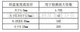
Remarks: 1. The standard involved in the document is the secondary standard in IPC-A-610 . The inspection method involved is obtained by the following magnification:
2 , the default components in the text are standard parts, based on this design of the pad and steel mesh.
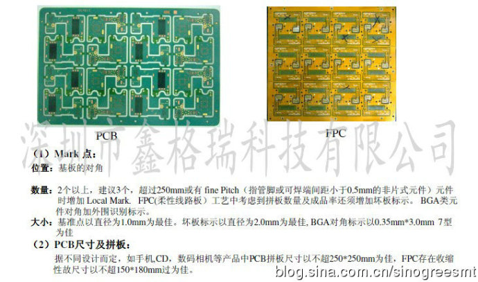
 1,         The manufacturability of the PCB .
2, Â Â Â Â Â Â Â Â The manufacturability design of the steel mesh.
In order to make the solder paste better formed after printing, the steel mesh should pay attention to the following requirements in thickness selection and opening design:
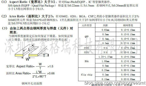
Â
3 , common components in the SMT process and its pad steel mesh opening design
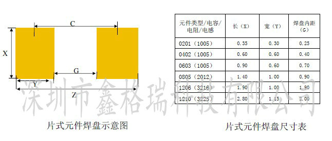
 ( 1 ) Chip component size: including resistance (exclusion), capacitance (discharge), inductance, etc.
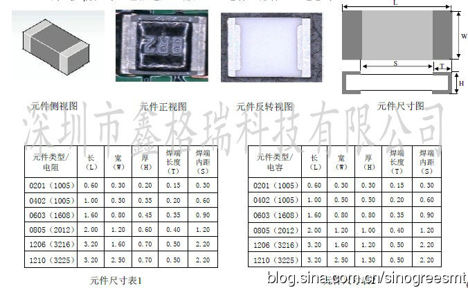
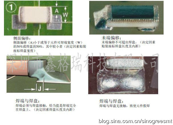
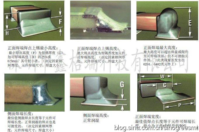
( 2 ) Soldering requirements for solder joints of chip components: including resistance (exclusion), capacitance (discharge), inductance, etc.
( 3 ) Chip component pad design: including resistance (exclusion), capacitance (discharge), inductance, etc.
    According to the component size and solder joint requirements, the following pad sizes can be derived:
( 4 ) Chip component stencil opening design: including resistance (exclusion), capacitance (discharge), inductance and so on.
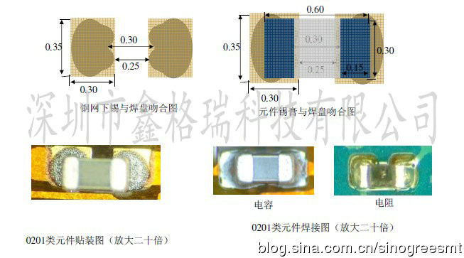
 ( 4.1 ) 0201 component steel mesh design:
        Design points: components can not be high, tombstone.
        The thickness of the steel mesh: 0.08-0.12MM , open horseshoe shape, the inner distance is kept 0.30 , and the total tin area is 95% of the pad .
( 4.2 ) 0402 component steel mesh design:
      Design points: components can not be high, tin beads, tombstones.
     The thickness of the steel mesh: 0.10-0.15MM , the best 0.12MM , the concave anti-tin beads with 0.2 in the middle , the inner distance is kept at 0.45 , the outer three ends of the resistor are added with 0.05 , the outer three ends of the capacitor are added with 0.1 , and the total tin area is the pad. 100% to 105%. (Note: Due to the different thickness of the resistor and capacitor, the resistance is 0.3MM , the capacitance is 0.5MM, so the amount of tin is different, which is a good help for the height of the tin and the detection of the AOI optical automatic detection)
0 ( 4.3 ) 0603 type component steel mesh design:
      Design points: components to avoid tin beads, tombstones, amount of tin.
      Steel mesh thickness: 0.12-0.15MM , 0.15MM is the best. The concave anti-tin beads with 0.25 opening in the middle maintain the inner distance of 0.8 , the outer three ends of the resistor plus 0.1 , the outer three ends of the capacitor plus 0.15 , and the total tin area is 100%-110% of the pad . (Note: 0603 type components 0402 , 0201 components are together when the thickness of the stencil is limited, in order to increase the amount of tin must be added in an external way)
1 ( 4.4 ) Stencils with a size greater than 0603 ( 1.6*0.8MM )
      Design points: components to avoid tin beads, the amount of tin.
      The thickness of the steel mesh is 0.12-0.15MM , and the concave shape of the 1/3 is opened to prevent the tin beads, and the amount of tin is 90%.
Surface Finishing ScreedVibrating ruler or surface finishing screed is a commonly used tool in construction machinery, mainly used to remove air from concrete in construction, scrape the concrete floor, and increase the density and viscosity of concrete. Vibratory rulers are used in a wide range of applications. The vibrating ruler, also known as the walk-behind vibrating ruler, can be divided into gasoline vibrating ruler and electric vibrating ruler according to power. Generally, a vibration ruler of about 2 meters is used the most.
Screed Vibrating Machine,Concrete Road Paving Leveling,Concrete Paver Leveling
Vibropac Machinery Co.,Ltd , https://www.vibropac-power.com